
Field Reflectance Spectrometer
Contents:
- Overview
- System Requirements
- Light Source Design
- Spectral Sensor Selection
- Mechanical and Electrical System Design
Overview:
Project Overview:
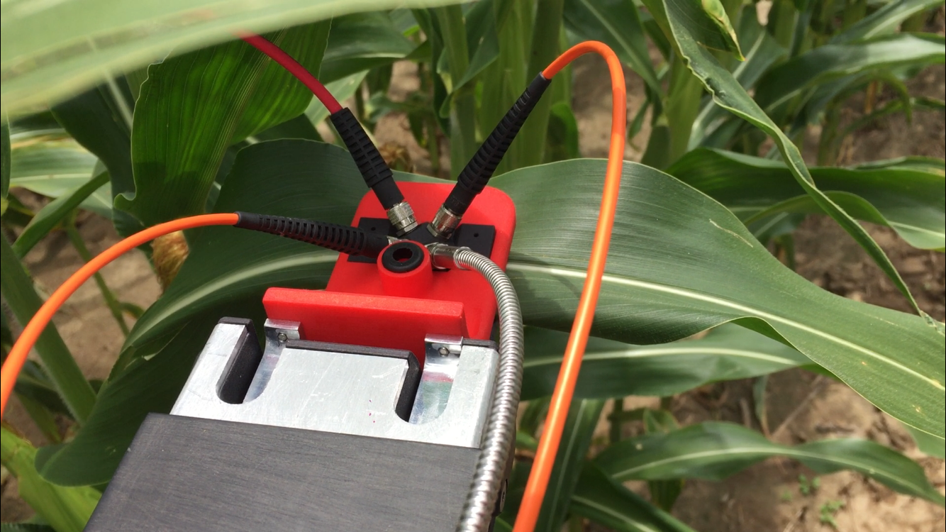
As a part of my Masters research work at Carnegie Mellon University, I developed portable reflectance spectrometer system capable of being mounted to an autonomous robotic system to take rapid spectral measurements of the stalks and leaves of various crops. This page details the mechanical design, sensor selections, and fabrication process of creating this field reflectance spectrometer system.
Spectroscopy Overview:
At the broadest level, spectroscopy refers to the measurement of electromagnetic radiation as a function of wavelength or frequency due to some physical phenomenon. More specifically, the field of spectroscopy attempts to study the specific interaction between matter and light to try to understand the atomic and molecular structure and chemical composition of various materials (such as moisture, chlorophyll, and protein content).
More specifically, reflectance spectroscopy is the study of reflected or scattered light from a material. Reflectance spectroscopy has a few key advantages that make it particularly fit for in-field, automated measurements. Firstly, the process is nondestructive to the sample. A reflectance spectrometer can simply be placed up to the surface of a material to take a reading, whereas other spectroscopy techniques (absorption and emission spectroscopy) usually require lengthy and destructive material preparation that must be performed in a laboratory setting. Furthermore, reflectance spectroscopy is relatively cheap to perform and readings can be done in a matter of seconds. Therefore, reflectance spectroscopy was chosen as a technique for collecting crop data by the autonomous ground robot developed in conjunction with my research work at the Robotics Institute at Carnegie Mellon.
Portable reflectance spectrometers contain three basic components used for the measurement of light: a light source, a diffraction grating, and a light sensor or detector. The light source provides the initial introduction of radiation that is projected onto the sample. It is crucial for the light source to emit a continuous spectrum of radiation that covers the wavelengths measured by the spectrometer. The diffraction grating takes in a stream of broadband light and refracts the different wavelengths of light at slightly different angles, in essence separating the light so that the sensor in the spectrometer can measure the intensity of individual wavelengths. Lastly, the light sensor or detector is used to measure the intensity of light projected onto it. These three basic components and how they fit into the general construction of a spectrometer can be seen in the figures below. The right figure demonstrates a spectrometer system that must be placed on the surface of the sample. The left figure demostrates a system that uses a bifurcated fiber optic cable to collect reflected light from a sample.
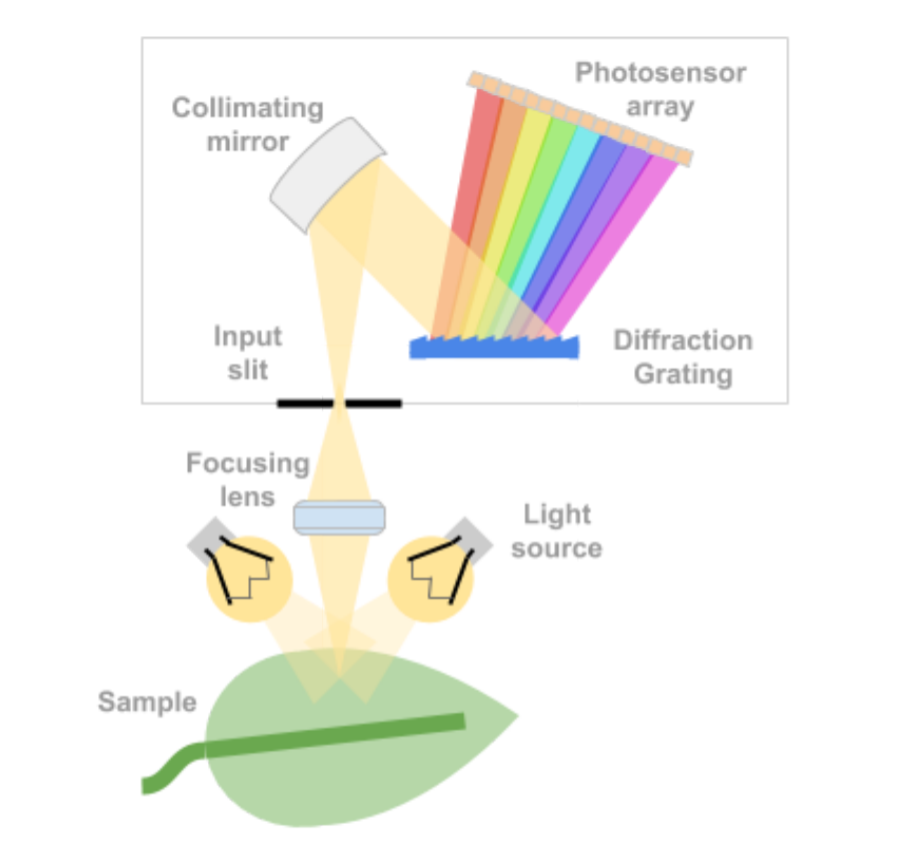
Basic construction of a reflectance spectrometer
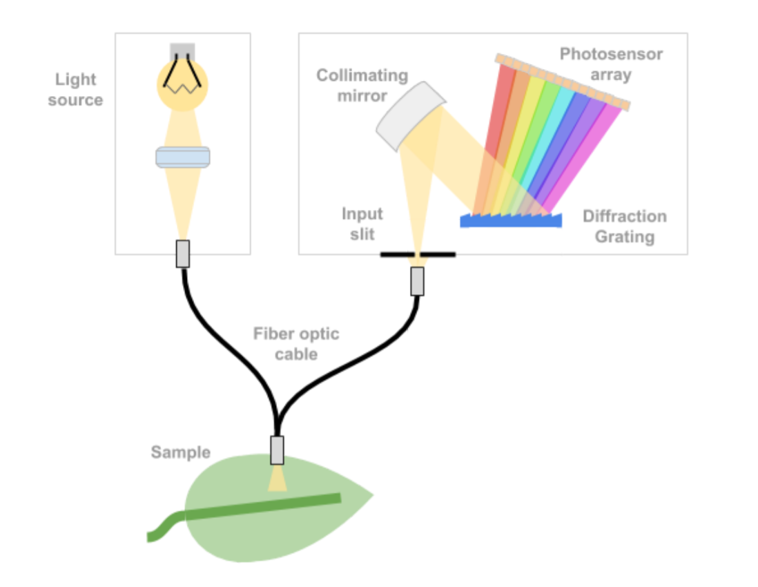
Reflectance spectrometer with fiber optic light collection
System Requirements:
A basic set of requirements for a portable, in-field reflectance spectrometer system was first created in order to drive most of the electrical and mechanical design decisions.
- Mass: Less than 5 kg
- Volume: Less than 5,000 cubic centimeters (no more than 30 cm in any dimension)
- Power: Less than 50 W to operate
- Wavelength Range: Must cover at least 400 - 2400 nm
- Spectral Resolution: Less than 2nm in VIS band, 5 nm in NIR band, 10 nm in SWIR band
- Cost: Less than $25,000 for entire system
The maximum mass of the system is mainly determined to allow for practical in field use. Anything above 5 kilograms would be too heavy and cumbersome to allow for quick and easy plant measurements. The maximum volume was determined in a similar way, as anything above 5000 cubic centimeters or 30 cm in any dimension would be too bulky to easily transport manually throughout the field. The maximum power is set to limit the draw from the robot’s on board battery while also being large enough to power the spectrometers as well as a potentially high power incandescent light source. The wavelength range is set to cover the visible light band (380 - 750 nm), the near infrared band or NIR (750 - 1500 nm), and most of the short wavelength infrared band or SWIR (1500 - 3000 nm). The spectral resolution is set at slightly above the industry standard to allow for high resolution reflectance light analysis. Lastly, a maximum cost is set at $25,000 to allow for quality components while also forcing the design to remain relatively low cost (compared to some high end sensors) for marketability and economic constraints from this project’s funding source.
Light Source Design:
The selection of a proper light source used in a spectrometer is crucial to the accuracy and consistency of spectral reflectance measurements of a sample. At the most basic level, the light source must emit electromagnetic radiation throughout all wavelength bands measured by the sensors in the system. Although there are many robust, high quality light source assemblies on the market that are designed and optimized for spectroscopy applications, these assemblies are often expensive and rather large when considering the strict size constraints on this spectrometer project. Thus I ultimately decided to design a custom light source for the reflectance spectrometer system.
Bulb Selection:
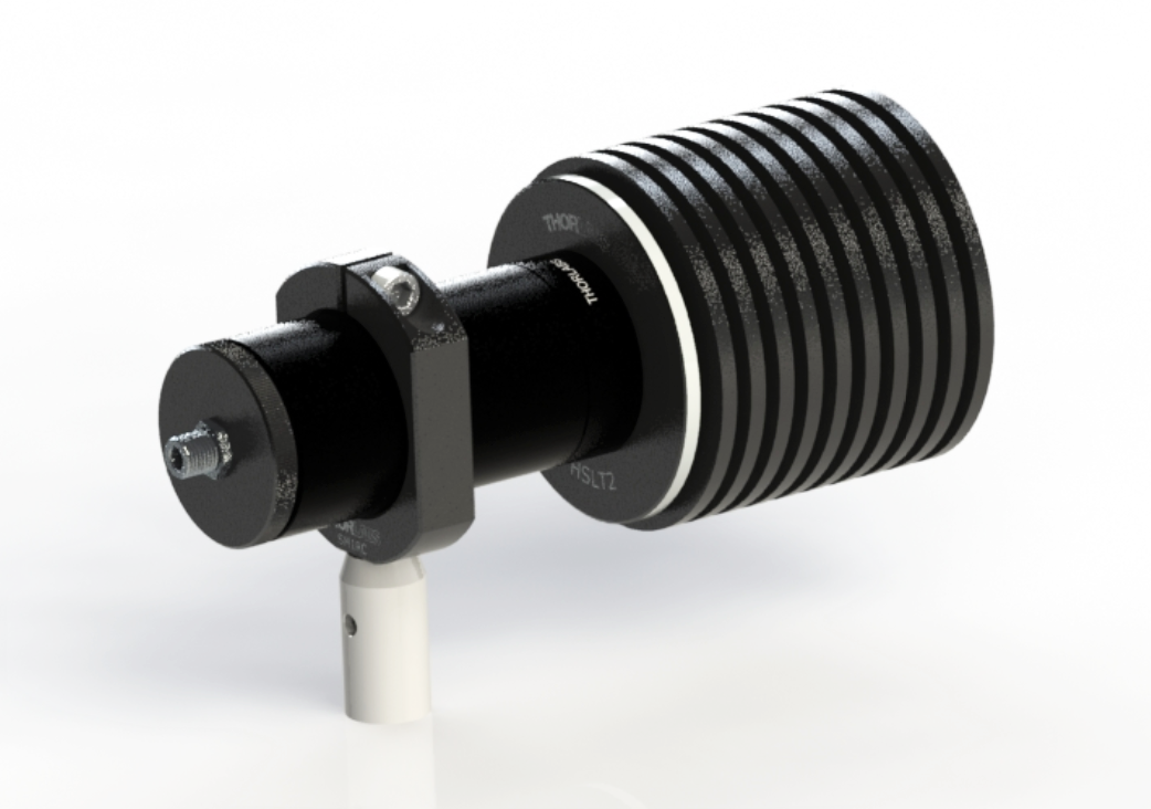
I selected the Thorlabs HEP3965 Broadband IR Tungsten Bulb, shown in the figure below. This bulb produces a broadband output from about 400 to 5000 nm at a color temperature of 1900 K, resulting in a peak intensity right around 1500 nm. The bulb comes mounted in a small TO-8 can with a reflector placed behind the filament for greater forward facing luminous flux. The bulb can be driven up to 3.5 V with a maximum current of 2 A resulting in a maximum power rating of 7 W. Furthermore, this bulb comes with a threaded mounting adapter allowing for easy installation into Thorlabs lens tubes. These components allow for greater precision in filament alignment and imaging onto the end of the optical fiber.
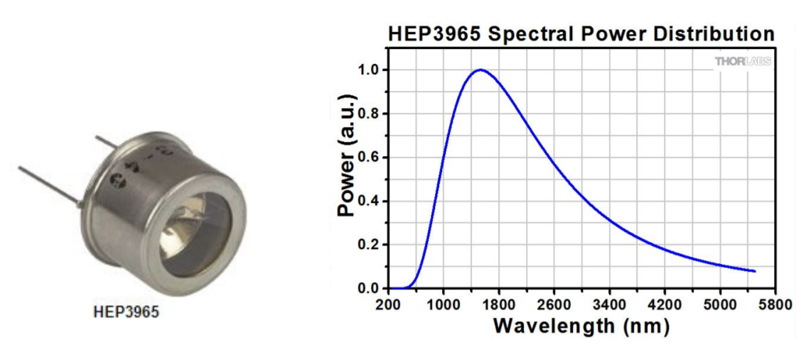
Thorlabs broadband IR tungsten bulb and spectral output
Light Source Assembly:
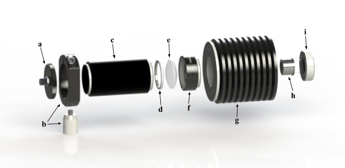
- (a) Thorlabs S120-SMA - Lens tube cap with internal SM1 threading and SMA fiber connector
- (b) Thorlabs SM1RC and TR1 - SM1 Lens tube slip ring and vertical mounting post
- (c) Thorlabs SM1S20 - 2" Long SM1 lens tube spacer
- (d) Thorlabs CMRR - Retaining ring for SM1 lens tube
- (e) Thorlabs LB1761 - N-BK7 Bi-Convex Lens with 1” diameter and 25.4 mm focal length
- (f) Thorlabs LB1761-ML Housing - Mounting tube for lens and retaining ring
- (g) Thorlabs HSLT2 - Passive heat sink lens tube with internal SM1 threading
- (h) Thorlabs HEP3965 - Broadband infrared tungsten bulb
- (i) Thorlabs HEPM - Mounting adapter for HEP3965 bulb
As seen in the exploded view above, the tungsten bulb (h) rests inside a thick, circular adapter plate (i) with external threading. This adapter plate is then mounted inside a heat sink style lens tube (g) with many radial fins for added heat expulsion and greater convective cooling during use. Because the interior of the heat sink lens tube and the exterior of the bulb adapter plate are both finely threaded, the position of the bulbs filament along the axis of the tube can be precisely controlled. Attached to the front face of the heat sink lens tube is a short mounting tube (f) for an N-BK7, a type of borosilicate glass, biconvex lens (e). The next component along the optical axis is a two inch long lens tube (c) to properly space the lens from the optical fiber. On the end of the lens tube spacer is a threaded cap (a) with an SMA fiber connecter to attach a fiber optic cable for light collection. The entire assembly is held in space by a vertical mounting post with a large slip ring (b) that tightly hugs the two inch lens tube. This vertical mounting post can be fastened to the base plate of the spectrometer housing for rigid attachment within the larger system.
Spectral Sensor Selection:
A variety of spectral sensors were surveyed, and the primary list that was considered is presented in the table below (ordered by price). The sensors that were ultimately selected for this application are highlighted and presented below the table.
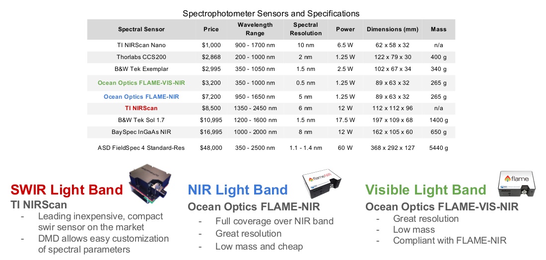
Ultimately, three spectral sensors were selected to be packaged within the overall reflectance spectrometer system in order to cover the entire wavelength band required by the project. It should be noted that the ASD FieldSpec 4 Standard-Res is an ideal product that captures the full wavelength range, has a small spectral resolution, and operates just below the maximum power limit. This system would be a fantastic choice for our research project's application, however the cost is well above the budget, thus a more creative and cheaper solution is needed.
Ocean Optics FLAME-VIS-NIR (Visible Light Band): This sensor was selected for its great spectral resolution, low mass and its packaged set of software tools for operation and data analysis.
Ocean Optics FLAME-NIR NIR Light Band): This sensor was selected for its full coverage of the NIR bandwidth, great spectral resolution, and low mass. Furthermore, it can easily be paired with the FLAME-VIS-NIR system from Ocean Optics shown above.
TI NIRScan (SWIR Light Band): This sensor was selected as it appears to be the leading inexpensive, compact SWIR sensor on the market. It is relatively cheap and comes with unique, customizable hardware and software to configure the wavelength range and spectral resolution.
Mechanical and Electrical System Design:

Mechanical:
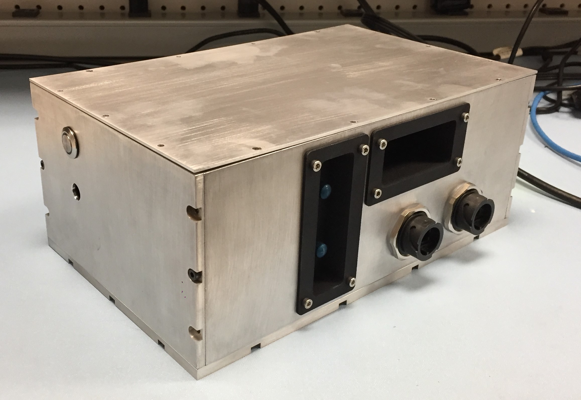
The overall reflectance spectrometer assembly is responsible for housing the three spectrometers, the custom light source, and all relevant electronics such as a USB hub, power regulators, and cooling systems. A final rendering is shown below next to a photo of the fully assembled system. The aluminum housing is 26 cm in length, 16.5 cm in width, and 11.5 cm in height for a total volume of 4933.5 cubic centimeters, or just below the maximum volume specified. The overall mass of the system is about 3.5 kg which is well below the maximum mass specified. A breakdown of the major components within the system is shown below:
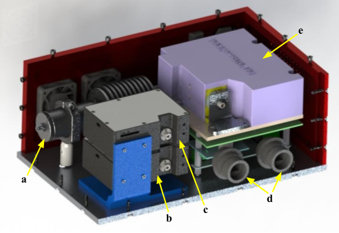
- (a) Custom broadband light source
- (b) Ocean Optics FLAME-VIS-NIR spectrometer
- (c) Ocean Optics FLAME-NIR spectrometer
- (d) Ethernet and USB bulkhead connectors
- (e) TI NIRScan spectrometer
The overall system housing is built out of six aluminum panels, which account for about 33% of the total mass, bolted together with M3 x 10 socket head cap screws that are slightly recessed into the faces of each panel to create a smooth, flat surface on all sides. Given the need for easy access to the fiber optic inputs of the three spectrometers from the exterior, two seperate 3D printed adapter plates are mounted to the front panel of the system that protrude into the interior of the housing with small openings for the three SMA fiber optic connectors. The fiber optic connector for the light source is accessible through a small hole on the left side panel of the housing.
USB and ethernet connections are provided through two rugged and sealable bulkhead connectors on the front panel. The TI NIRScan spectrometer is digitally interfaced over ethernet while the two Ocean Optics spectrometers are accessed over USB. A sealed four pin electrical connector is mounted to the back panel of the housing to provide power to the entire system. Additionally, a rocker switch is positioned next to this connector to turn on and shut off power to the spectrometer. Two fans are also mounted to the inside face of the back panel to provide convective air flow to cool the heat sink around the light source. Similarly, two fine filter screens are placed on the outside face over the fans to prevent debris from entering
Electrical:
Two DC-DC converters are mounted underneath the TI NIRScan to provide regulated power to the subsystems within the housing. A CUI converter (PYB20-Q24-S3-T) with a 9-36 V input range and 3.3 V, 5 A output is used to power the custom light source. The output voltage is trimmed up to 3.5 V using a resistor in line between the trim and Vo+ pins on the converter. The tungsten bulb is the only load powered off of this supply as to mitigate noise and disturbances in the output signal. A circular push 30 button switch is located on the left panel above the SMA connector to the light source to control power to this DC-DC converter. Additionally, a second CUI converter (PQA30-D24-S12-T) with an 18-36 V input range and 12 V, 2.5 A output is used to power the remaining subsystems; the TI NIRScan spectrometer, a USB hub to power the two Ocean Optics spectrometers, the two cooling fans, and a small LED on the light source switch.
The four pin power connector on the back panel splits to provide positive and ground lines to each of the two converters. The set of wires feeding to the 12 V output converter is designed to receive ~24 V unregulated power straight from the battery pack on the robotic platform. The set of wires feeding to the 3.5 V output converter has an input range of 9-36 V so it can take in either ~24 V unregulated power or power from the 12 V regulator on board the robot.