Optimal Grasp Pose Detection on Leaves
Overview:
In order to grasp sorghum (and corn) leaves using the custom manipulator developed in "Robotic Leaf Grasping Manipulator", a valid grasp pose must first be determined. This process in large part depends on the inverse kinematics of the manipulator as well as the pose of the target object. Once a set of leaves have been detected using the process described in "Real-Time Leaf Detection Using Stereo Camera", we can use the estimated 3D models of the leaves to calculate "optimal" grasp poses. This page details the challenges from the limited degrees of freedom of the custom manipulator and then describes algorithms used to quantify the quality of various potential grasp poses.
Constraints Due to Limited Degrees of Freedom:
In most robotic manipulation tasks, grasp point detection is based heavily on the geometry and pose of the target object. It is also the case that the kinematics of the robotic manipulator have a significant impact on the feasibility of detected grasp points. For example, a robotic arm with six or more degrees of freedom can essentially move its end effector to any position and orientation within the reach of the robot, making almost all detected grasp points in the scene feasible. However, given a manipulator with a limited number of degrees of freedom, a subset of seemingly ideal grasp points may be unachievable. In the case of our custom leaf grasping manipulator, only three degrees of freedom are used to move the leaf clamp end effector to a potential grasp point. The kinematics of this custom manipulator allow for the positioning of the end effector to any point in 3D space but the resulting orientation is uncontrollable and dictated by the system geometry, as shown in the figure below. Therefore, the manipulator may position the leaf clamp at a grasp point, but the resulting angle of the clamp may make a successful grasp impractical or even impossible.
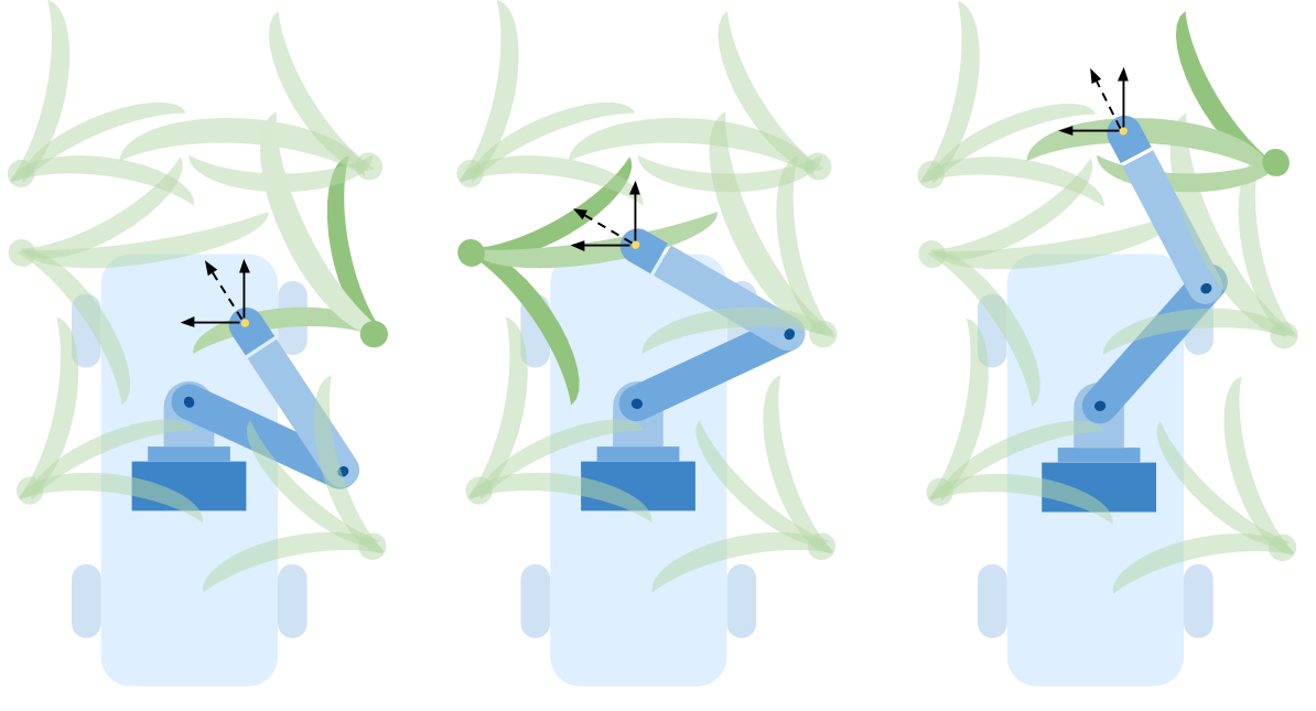
Uncontrollable end effector orientation at various grasp points
Graspability Metric:
Given the challenges and constraints from the limited degrees of freedom of the manipulator, it is convenient to develop a graspability metric that proactively ranks the feasibility of various grasp poses. Therefore, the best grasp poses can be extracted from a large set of poses along a leaf based on the points that rank the highest in terms of graspability. Naturally, the question then arises, what defines graspability in this context? Here, graspability is defined as a measure of the quality of a leaf’s pose as it relates to the kinematics and constraints of the manipulator. The remainder of this section is dedicated to creating a compact function, called the graspability function, that will produce a normalized score that reflects the estimated quality of a grasp at a specified point along the leaf. In order to develop this function, some standard notation must first be considered. In the figure below, a sample leaf is shown along with various detected leaf points along its surface.
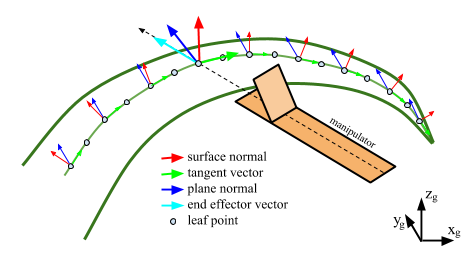
Leaf point notation for graspability metric
At each leaf point, r, three unit vectors are present: the surface normal,
ŝr, the tangent vector, t̂r, and the plane
normal, p̂r. When a leaf is detected from the parabolic RANSAC leaf
detection algorithm described in
"Real-Time Leaf
Detection Using
Stereo Camera",
these three unit vectors are calculated for each point as follows. The plane
normal, p̂r, has actually already been found in Step 1b in the parabolic
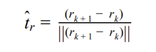
RANSAC algorithm. The tangent vector, t̂r, is found by solving for the
vector between the current point, rk, and a neighboring point,
rk+1 then normalizing as shown in the equation:
Lastly, the surface normal, ŝr, can then be found by taking the cross
product between the tangent vector and the plane normal, as shown in the equation below, to create an
orthogonal set of axes centered at the leaf point.

Also of importance is the end effector vector, ĉr, a unit vector whose
direction is parallel with the length of the last link of the manipulator when the end effector has
reached the leaf point. The calculation of this vector comes from the inverse kinematics of the
manipulator and is shown in the section titled "Inverse Kinematics of Manipulator" below.
Next, it is useful to create a binary function, gr , which determines whether a
leaf point is graspable given its surface normal. This is necessary as portions of a leaf with a large
angle between the surface normal and vertical vector cannot be grasped by the end effector. In other
words, the more vertical a part of the leaf becomes, the more difficult it is to grasp with the leaf
gripper. This binary grasp function is shown below:

Here, the θmax parameter can be set to create a threshold on leaf points that
are considered graspable based on the angle the surface normal makes with the vertical vector. During
testing of the manipulator in the field, a value of π/3 or 60 degrees was used for
θmax. The figure below provides a visualization of the raw point cloud shown in
green as well as the surface normals of all detected leaf points. The surface normals are shown in
yellow if they are considered graspable by the binary graspability function and red if they are
considered not graspable.
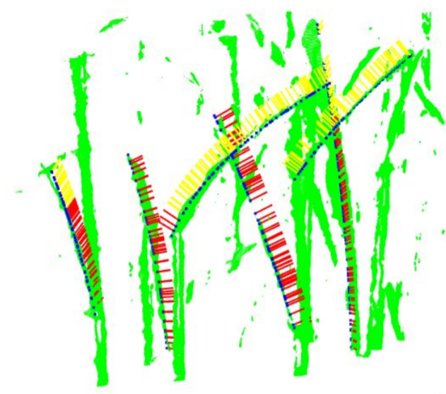
Visualization of the binary grasp function (yellow = graspable, red = not graspable)
With all of the information presented above, a mathematical definition of graspability can now be created in the form of the graspability function shown below:

This function essentially outputs a normalized score that evaluates the quality of a grasp based on
the angle between the end effector vector and the plane normal as well as the angle between the surface
normal and the vertical vector. The first dot product term,
|ĉr·p̂r|, returns a value between zero and one
where an output of zero represents a 90 degree difference between the end effector and the plane normal,
and an output of one represents the case where the vectors are parallel, the best scenario. Here,
α is known as the yaw error gain and varies the effect that this angle difference
has on the overall output. Similarly, the second dot product term,
|ŝr·ẑg|, returns a value between zero and one where an
output of zero represents a 90 degree difference between the surface normal and the vertical vector, and
an output of one represents the case where the vectors are parallel, the best scenario. β
is known as the roll error gain and varies the effect that this angle difference has on the
overall output.
The first term in the function, 1/(α+β), normalizes the result so that the graspability
score is between zero and one, where a score of one is considered best. The second term,
gr(ŝr), is again the
binary grasp function which will cause the entire equation to equal zero when a point is determined to
be ungraspable. When a point is graspable, the binary grasp function has no effect on the score. To
summarize, the function above is presented again below with a summary of each term.

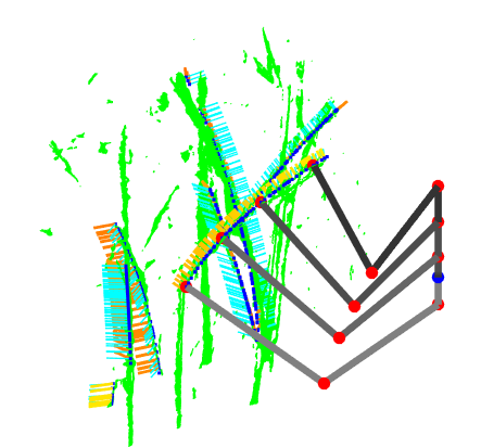
From field testing, it was determined that the angle between the leaf plane normal and vertical vector was the most important component of the graspability function. This angle difference is visually depicted in the figure below. The plane normal vectors are plotted in light blue on each detected leaf midrib point. the end effector vector is plotted in a color ranging from yellow to red based on the magnitude of the angle difference between the two vectors.
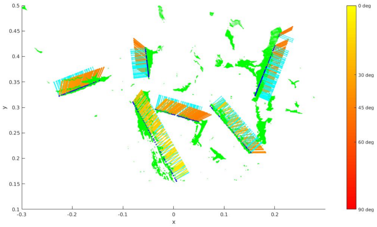
End effector vectors plotted over leaf plane normals
Invervse Kinematics of Manipulator:
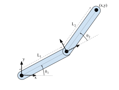
In order to determine the joint angles that will position the end effector to a given location in space, the inverse kinematics of the system must be solved. This is a crucial process as the robotic arm is controlled by passing in the desired joint angles to the controllers of the revolute joints. A simple model of a planar two link kinematic chain is shown in the figure below.
Simple planar two link kinematic chain model
Given that the derivation of the inverse kinematics of such a system is so common in introductory
robotics texts, the majority of the steps have been excluded and the final form is simply shown instead.
The two joint angles, θ1 and θ2, are calculated as shown
in the equations below.

After these two joint angles have been found, the end effector vector referenced above can be solved for using the equation below.

A basic simulation was created to test the accuracy of the inverse kinematics. A visualization including the manipulator configuration for multiple grasp points along a leaf is shown in the figure below. As before, the plane normals are displayed in light blue while the end effector vectors are shown in the yellow to red gradient.
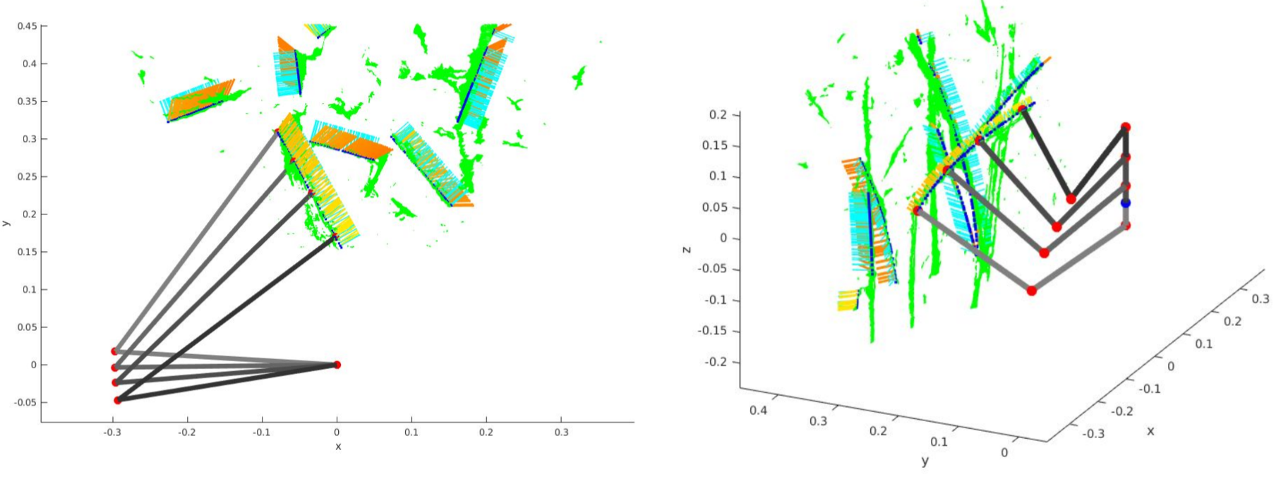
Manipulator configurations for multiple grasp points (left: top view, right: 3D view)
The inverse kinematics are solved online in C++ on an Intel NUC i7 processor in an average of about 50 microseconds. During the grasp point detection pipeline, the two joint angles are calculated for each of the potential grasp points in the scene. With an average of about 200 potential grasp points, the entire process of solving the inverse kinematics for all points takes about 10 milliseconds or one one-hundredth of a second.